This is a proposal to the people who make FPGA versions of the CoCo 3’s GIME chip.
I was recently reading about the Amiga’s Copper chip. I thought something similar could be added to a GIME implementation. The following is my idea, for what it’s worth.
Addresses used:
FF99, Bit 7
Horizontal retrace update enable
FFEA-FFEC
Address (24 bit) table start
Table format:
0 byte
Scan line
1 byte
GIME register number
2 byte
New value
Repeating.
Function
If enabled, during the vertical retrace, the 24 bit table start address is loaded. Then the first byte of the table is deference. If the scan line value (table byte 0) is $FF, then the new value is written to the register number. The table pointer is advanced (by three bytes) and writes are repeated until the scan line is no longer $FF. This allows you to set any video registers before they are latched for the frame.
During every Horizontal retrace the scan line declared in the table is compared to the current scan line. If there is a match, the table value is written to the specified GIME register. Then the next table entry scan line is loaded.
If the scan line does not match, the process is paused until then next horizontal retrace.
If there is time, multiple GIME registers can be changed during horizontal retrace.
Register number zero refers to $FF90 (Initialization register #0). It goes up from there.
Register numbers $FE will trigger an FIRQ or IRQ. Nothing will be written to an internal register. Bit 6 will determine which interrupt is generated ($FF92 or $FF93).
Register number $FD will cause the GIME to reload the video start address from $FF9D and $FF9E. Nothing will be written to an internal register.
Example Programs
I implemented the above in a private MAME branch. I wrote some demos and made these screen captures. All this code can be found here.
COLOR64/BAS:
In BASIC, switch to HSCREEN 2 and draw a grid of 64 circles. Eight every row, for 8 rows. Use palette index 1 to 8 for every row. Load in an assembly language program to install a horizontal sync table to update the palette color to show all 64 colors on the screen at the same time.
In BASIC, switch to HSCREEN 2, then load a binary file. This file contains:
Image data to be loaded in the Hi-res screen memory.
The first 52 lines are 128 bytes wide
The rest are 256 bytes wide.
Hsync table to switch to 256 byte wide video at line 52.
Code to install hsync table and turn it on.
Then the BASIC program will update the horizontal scroll register in the table to match the horizontal joystick position.
In BASIC switch to HSCREEN 2, Draw random circles. Load hsync table and enable it. Near the bottom of the screen the GIME is instructed to switch to text mode and change the display address to be the bottom of the 40 column text screen.
Repeat drawing circle to the graphics screen and printing text to the 40 column screen.
In BASIC load binary from disk, wait for disk to stop spinning. Switch to HSCREEN 2 and have BASIC draw random circles. Setup horizontal table to trigger IRQ interrupt on scan line 100.
Interrupt service routine quickly sets all palette registers to zero. Then immediately restore RGB palette values. Repeat on next frame.
We usually do a poor job of playing complicated game we don’t know. But both of us decided to really learn this game and try to play it well. The game has a sprawling world and I quickly decided I needed a map. So I made one. I like to share so here it is.
It was recently brought to my attention that Darren Atkinson has a really good summary of the invalid register exchange and transfer opcodes in the 6809.
So good, that I should use the information to make MAME’s 6809 better match real hardware.
That will be a future post. In the mean time, I wrote a little program to exercise all of the invalid combinations and print results to the CoCo’s screen memory. This way I can, eventually, verify the implementation.
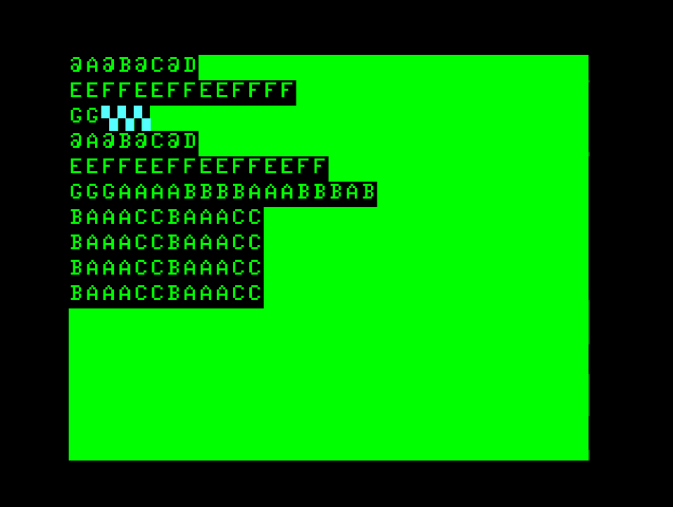
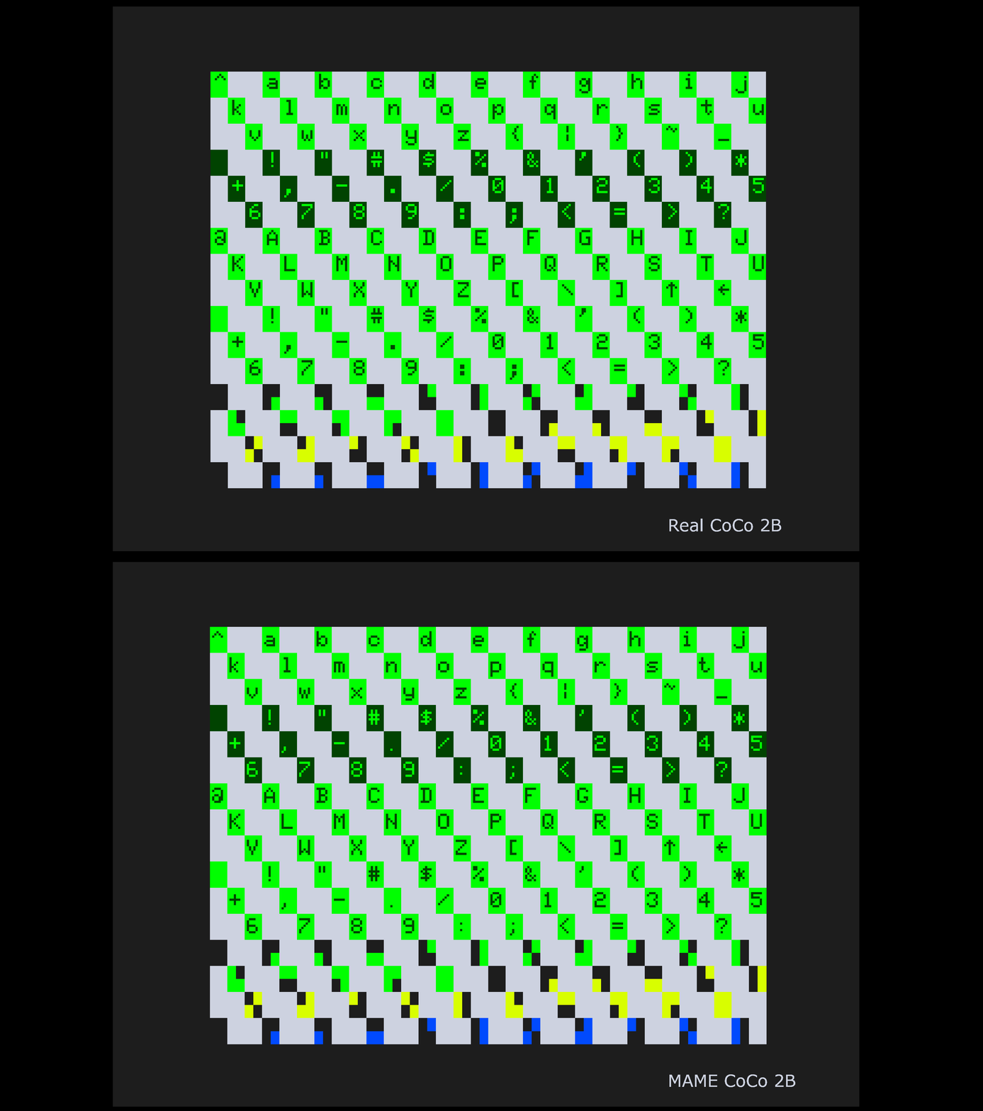
Here is a screen shot from a real CoCo 2B with a 6809 running my program:
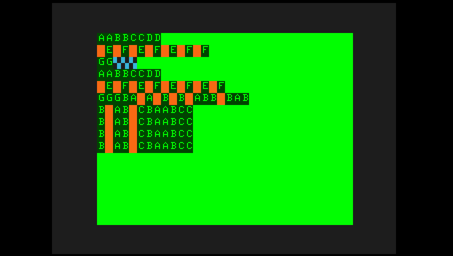
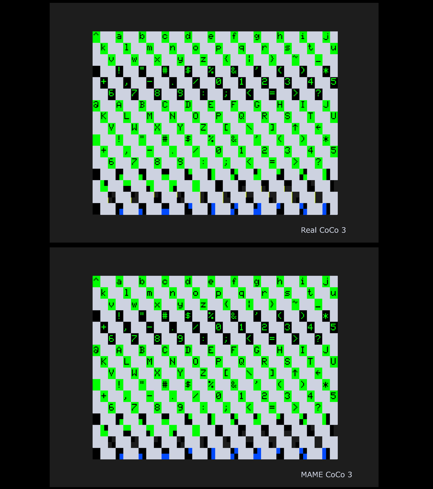
And here is a screen shot form a real CoCo 3 with a 6309 running the same program:
By “invalid”, I mean the combinations of registers that Motorola didn’t document. Combinations like specifying different width registers when exchanging or transferring. Or the use of the register bit patterns not defined by Motorola.
I was recently informed of some inaccuracies with the various VDG text screens emulated in MAME. I also recently acquired an RGB2HDMI. This device is a very configurable retro computer video to HDMI device. One nice feature it has is to write the frame buffer to a PNG file.
Using this device I can capture pixel perfect pictures of my CoCos and compare them to what MAME currently produces.
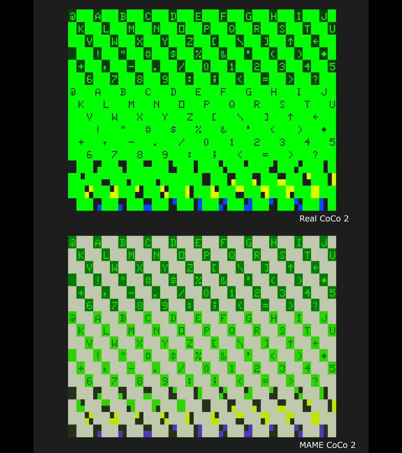
First, here is the comparison between a real and MAME emulated CoCo 2.
The stem of the number ‘3’ is too short in MAME.
The “E” stem is too short.
The “F” stem is too short.
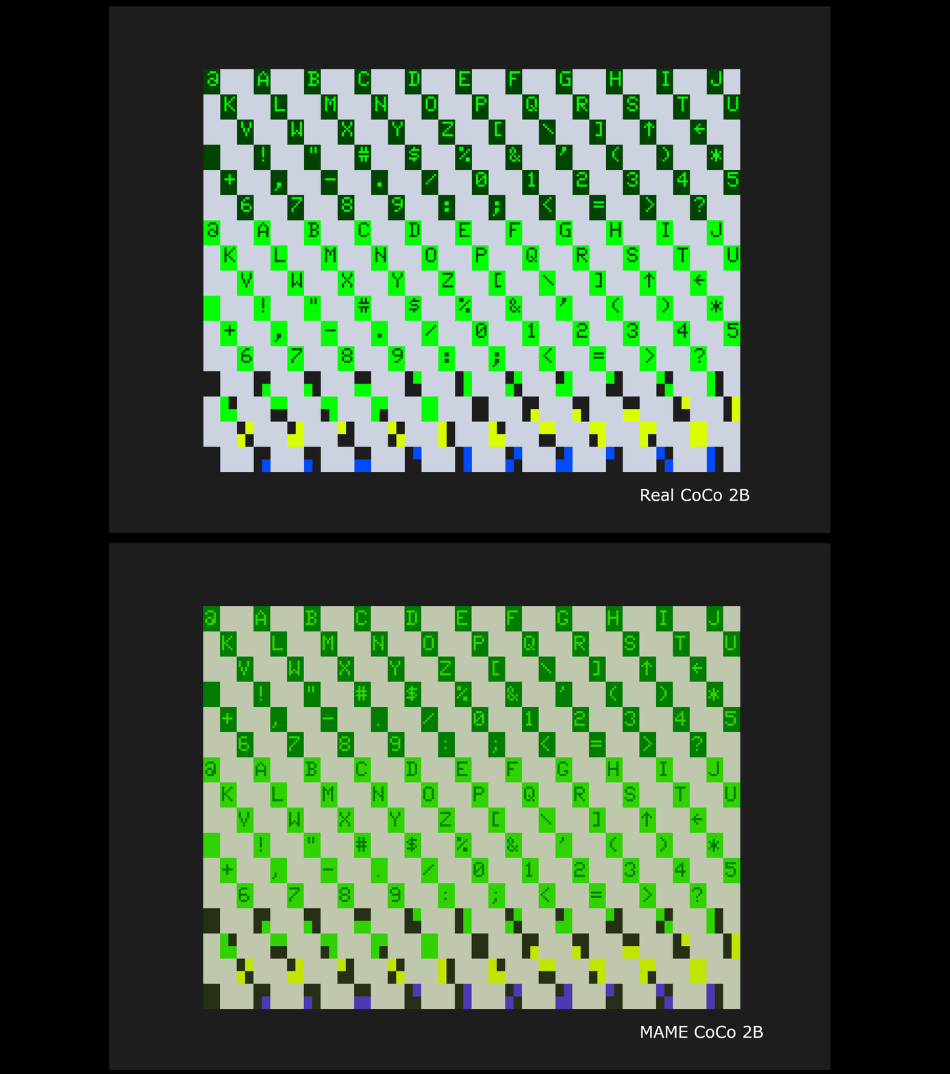
Next is the CoCo 2B in normal mode.
Over all the characters need to be pushed one pixel to the right and one pixel up to properly fit in their boxes.
The ‘@’ has an extra pixel.
The ‘G’ is the wrong shape.
The ‘J’ has an extra pixel.
The pound sign has extra pixels.
The dollar sign has extra pixels.
The apostrophe is missing some pixels.
The comma is missing some pixels.
The period is missing some pixels.
The three is missing a pixel on it’s stem.
The ‘6’ is the wrong shape.
The ‘9’ is the wrong shape.
The colon is missing some pixels.
The semi-colon is missing some pixels.
Next is the CoCo 2B in lowercase mode.
Over all the characters need to be moved one pixel up and to the right. Except the lowercase J. It only needs to be moved one pixel to the right.
The lowercase letter g is the wrong shape.
The lowercase letter m has an extra pixel.
The lowercase letter p is the wrong shape.
The lowercase letter q is the wrong shape.
The lowercase letter t is the wrong shape.
The lowercase letter w is the wrong shape.
The lowercase letter y is the wrong shape.
The pound sign has extra pixels.
The dollar sign has extra pixels.
The apostrophe is missing some pixels.
The comma is missing some pixels.
The period is missing some pixels.
The ‘3’ is missing a pixel on it’s stem.
The ‘6’ is the wrong shape.
The ‘9’ is the wrong shape.
The ‘@’ has an extra pixel.
The colon is missing some pixels.
The semi-colon is missing some pixels.
The ‘G’ is the wrong shape.
The ‘J’ has an extra pixel.
Next is the CoCo 3 in normal mode.
Over all, the characters need to be moved a pixel up.
The comma also needs to be moved one pixel to the right.
The number 9 has an extra pixel.
Last is the CoCo 3 in lowercase mode.
Over all the characters need to be moved one pixel up.
The lowercase letter g is the wrong shape.
The lowercase letter i is the wrong shape.
The lowercase letter j is the wrong shape.
The lowercase letter m has an extra pixel.
The lowercase letter p is the wrong shape.
The lowercase letter q is the wrong shape.
The comma need to be moved to the right one pixel.
The numeral 9 has an extra pixel.
Special thanks to Pedro Pena for a screen capture.
MAME 0.246 is the first version to contain the fixes for the above.
An interesting bug appeared on MAME Testers recently. The bug linked here is really simple. OS-9 wont boot on a copy protected disk image. The solution also was simple: properly emulate the delay between issuing a write command, and the INTRQ that happens when the write protect notch is covered.
But how long of a delay should it be? The floppy disk controller chip data sheet does not specify what is normal. I wish I had an oscilloscope to measure things like this, but I don’t. So I had to get tricky.
I wrote a Color Computer program that writes to a write protected disk on purpose. Normally after you issue the command to write to a sector, you prepare to start writing and then wait until the disk is ready. But if you know the disk write will error becuase of a write protect notch, all you really have to do is count. That is what I did, initiate write and then count forever:
pragma 6809
opt cd</p>
<p>start
org $6000
count fcb 55
error fcb $55</p>
<p>begin
orcc #$50 turn off interrupts, keep motor spinning
clrb clear counter
ldx #vector_return
stx $0983 load my NMI vector routine
lda #$ff
sta $0982 Enable NMI flag to vector
lda $ff48 reset status of 1793
lda #$A0
sta $FF48 do write sector command</p>
<p>; disk should be write protected.</p>
<p>loop
incb
bra loop</p>
<p>vector_return
stb count
lda $ff48
sta error
andcc #$AF enable interrupts
rts
end begin
The loop will not actually count forever. When the write fails, the Floppy Disk Controller will produce an Interrupt Request signal. On the Color Computer this is tied to the Non-Maskable Interrupt line. This will stop the loop and run my NMI handler. The records the counter and status to make available to a BASIC program for further processing.
I now have two results from different Floppy Disk Controllers: 20 and 19. With a 5 cycle loop counter, this comes to a delay of about 111 microseconds. I show my work here.
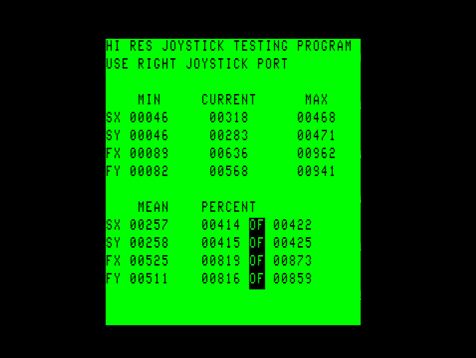
Thanks to a few friends I’ve been able to upgrade my hi-res tester to support the CoCo Max III interface. It is a device similar to the Tandy Hi-res interface, but is triggered differently.
Here is what MAME is doing as of today for the CoCo Max III interface:
Speed
Start Value
End Value
Length
Slow
67
483
416
Fast
67
483
416
After going over the data here is what I am going to change MAME to do:
Speed
Start Value
End Value
Length
Slow
29
243
214
Fast
57
486
429
You can see the new values are nearly the same as the previous values, but I think it is an improvement to use values verified on actual hardware.
I was recently told about a bug in MAME’s implementation of the Tandy Hi-Res Joystick interface. The author of C-III Pages (an early desktop publishing application for the Color Computer) discovered the mouse cursor would only go 7/8th across the width of the screen.
This means it is now time to really try to understand the device. Reading the code in MAME doesn’t really tell the whole story, and none of the values that are chosen are explained.
So I did what I always do, I wrote a test program to run on real hardware. https://github.com/tlindner/HiRes-Interface-Test
This program uses a slightly modified version of the sampling code found in most software. It does not do any scaling of the returned values to fit within the screen width or height. It leaves them raw.
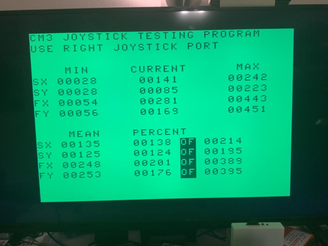
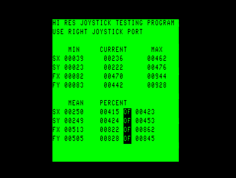
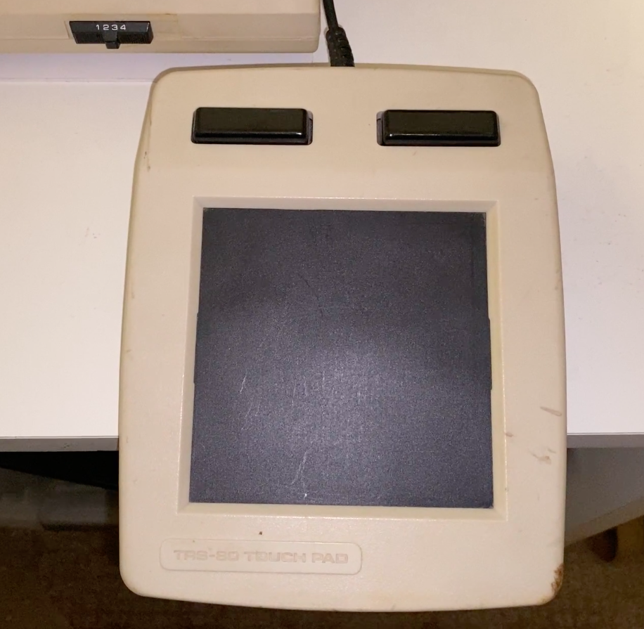
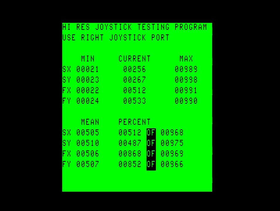
I have in my possession four “joysticks” to test. A black beauty, a delux joystick, a C&H joystick, and a Koala Touchpad. The testing procedure was to start the program and wiggle the joystick while looking at the graphic screen (the G command). When I filled in as much as the four rectangles as I could, I returned to the text screen and took a screen shot.
Black Beauty
Deluxe Joystick
C&H Joystick
Koala Touch pad
The Kola touch pad had the weirdest response to both versions of the sampling routine. See the image below and notice how much noise is in the bitmaps:
Here is what MAME is doing as of today:
Speed
Start Value
End Value
Length
Slow
99
805
706
Fast
99
805
706
After going over the data here is what I am going to change MAME to do:
Speed
Start Value
End Value
Length
Slow
40
475
435
Fast
80
950
870
Hopefully this will fix the bug in MAME that affects C-III Pages and not cause any regressions.
If you want to run the program your self with your own interfaces and joystick, I would love more data. I am especially interested in what the 1 and 2 button Color Mice do.
I would also like to get values from the Color Max 3 hi-res interface. If uses the same method, but the RC values are different in the circuit.
The Color Disk EDTASM assembler has the option of writing a symbol table to the end of binaries it produces. You enable the feature by including the /WS switch during assembly to disk. The symbol table can be used by the stand alone ZBUG debugger.
Invoking the switch will add extra data after the LOADM post-amble. Here is how that data is formatted. First is the header. This is always 5 bytes in length.
The show where we deep dive into a very specific 6809 assembly language topic.
Today we’re talking about calling subroutines. Subroutines are a very important aspect to programming. When ever you find yourself needing to do the same thing in two different parts of your program your best bet is to create a subroutine for that function. This process is so fundamental it has a name: refactoring.
There are many instructions to facilitate this. But the today we’ll be investiagting Branch to subroutine, and jump to subroutine. The branch version is used in position independant code, and also has a faster, shorter version for smaller branches.
JSR with no parameters
Let’s first talk about a subroutine that requires no parameters to be passed. The JSR instruction will push the address of the next instruction to the stack and then pass control to the subroutine.
The RTS instruction will pull two bytes off the top of the stack and jump to that memory location.
These two instructions are what enable calling subroutines in 6809 assemble language.
For example, let’s say we’re writing a game and we want to write a subroutine that displays the text GAME OVER in the center of the screen.
Here we see the code for a mini game ending. Let’s dig in deep to the specifics
• We execute the jsr instruction. It will push the address of the next instruction on the stack and jump to the operand.
• Do the work of the subroutine. This will copy some text to the middle of the VDG screen.
• Then return to the main program
JSR with calculated address
Sometimes you want to branch to different subroutines based on a condition. One method to do this is with a table of of subroutines. For example:
• I load a previously calculated random number that will be 0 or 1.
• Then multiply it by two.
• I add that value to the base address of the subroutine table.
• Then jump to that specific subroutine.
• After the subroutine finishes, it returns to the main program.
Parameter passing
Most of the time a subroutine will take parameters. These are values that change how the subroutine functions. In the example we’ve seen so far we may want to change the subroutine to make the text it displays variable. We also may want to have the text’s final position variable. Let’s go over some methods of passing these parameters to our subroutine.
JSR fixed memory locations
A simple, non-position independant method of passing parameters to a sub-routine is by using fixed memory locations.
• load the registers with the parameters
• call the subroutine
• notice how the registers are all setup ready for the function to be done.
• and return to the main program.
JSR stack
The stack is also a good way to pass parameters to a subroutine. Since the return address is already stored on the stack it makes sense to put the other parameters there.
• Push the two parameters onto the stack
• Call the subroutine
• Pop the return address off the stack
• pop the parameters off the stack
• perform the function
• transfer the return address to the pc register and return to the main program.
JSR post data
The last method we’ll discuss is when you put the data to be passed after the subroutine call. Care must be taken to return to the proper address when done with the subroutine.
• First we call the subroutine
• immediately after the call, we put two bytes of a destination address and then a string of characters with a zero terminator.
• In the subroutine we load x with the address that was pushed onto the stack. This is technically the return address, but if we used it as such, we would return to data, not code.
• Then we load register Y with the address of the text string
• Then we load register X with the address of the text destination.
• We perform the function
• Then we return from the subroutine by transferring the Y register to the PC register which will conveniently be the proper return address.
That’s it for this episode. I hope you had a good time learning about subroutines and all the various ways you can pass parameters to them.
Recently I was investigating why the Color Computer 3 version of Arkanoid didn’t make any ricochet sounds when the ball bounced off an object in MAME. For an example of the game working properly see this video here:
After talking with the author of the game (Steve Bjork: name drop) he said the sound in question was being played by using the timer interrupt system in the machine. I disassembled the FIRQ handler and quickly found the problem. His playback routine did two things: it wrote a value to the DAC, and determined the proper amount of time to wait before the next DAC update. It did not update the DAC at a constant frequency.
Here is what the ISR did, in the order it did them:
1. Acknowledge the interrupt.
2. Write the new timer delay to the register
3. Enable the interrupt again.
4. Write the value to the DAC.
5. Determine the next timer delay and store it for the next interrupt.
The problem was the first time the ISR was called: It wrote a zero for the amount of delay to the next interrupt, because the delay isn’t properly determined until then end of the ISR. Documentation about the CoCo 3 hardware says this should stop the timer interrupt. And that is what MAME did. But this is not what real hardware does. On real hardware you get an immediate re-aserting of the interrupt when the timer value is set to zero. On the second interrupt the sound system is properly initialized, real timer values were being written, and samples are being sent to the DAC.
In order to find this problem I wrote some test programs. This helped me to fix the above bug, and also discover another bug in MAME. MAME tightly coupled the pulling of the F/IRQ line with setting the F/IRQ flag. On real hardware turning off the interrupt has no effect whether the flags are set.
The archive below is the test code I wrote. Three different routines that set up the timer interrupt. Every time the interrupt is fired the address $400 is incremented.
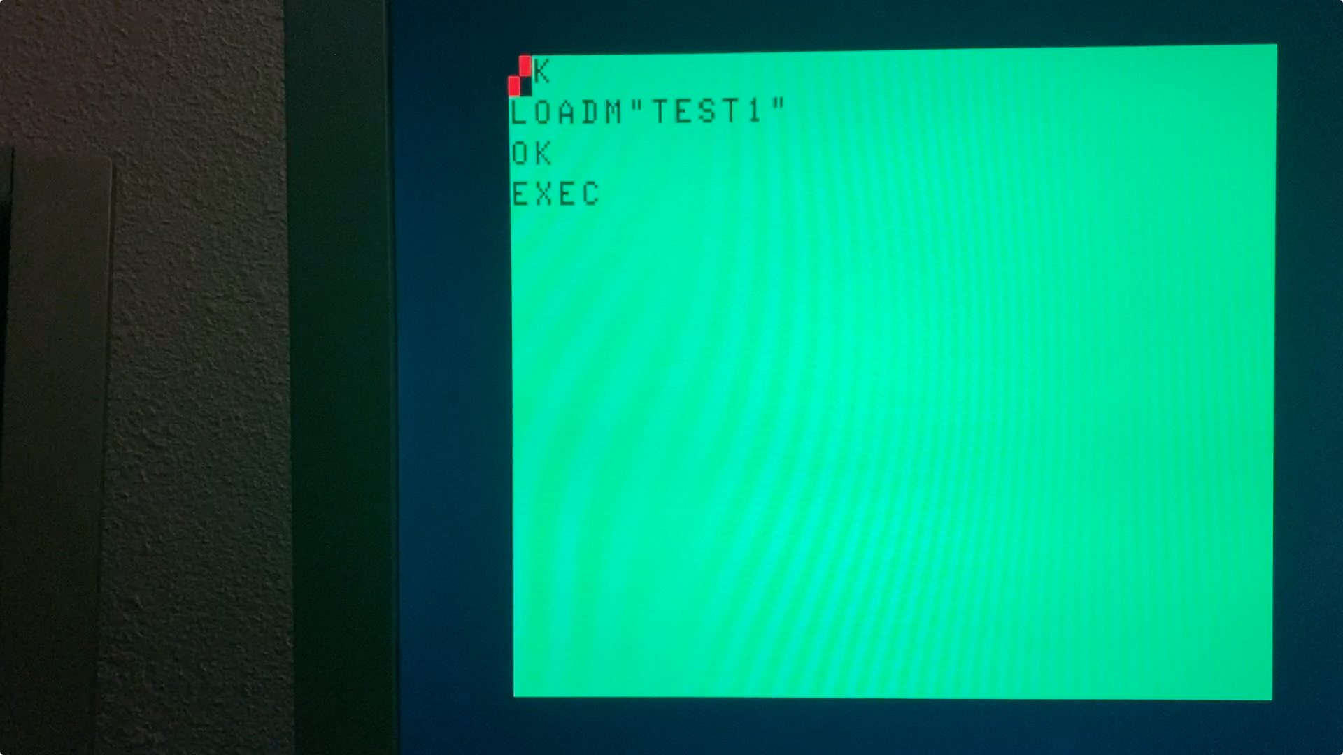
TEST1 sets up the slow timer with a value of $FFF. TEST2 sets up the fast timer with a value of $FFF. TEST3 sets up the slow timer with a value of $0. All three programs use polling to check if the timers fired (bug #2). TEST3 is the program that test a timer value of zero (bug #1).
Included are video files from my Color Computer 3 with an ’86 GIME. They show what the program display as they are running.