Reverse Engineering the CoCo Speech/Sound Cartridge Sound Activity Circuit
The Color Computer Speech/Sound Cartridge (S/SC) was one of the more ambitious peripherals Tandy produced for the CoCo line. It packed a TMS-7040 microcontroller, an SPO256-AL2 speech synthesizer, an AY-3-8913 programmable sound generator, and 2K of RAM into a single cartridge. It was complex enough that most CoCo owners never fully understood what it was doing.
I am a contributor to the Mame emulator project, and I maintain the CoCo SSC slot device. It emulates the TMS-7040, the SPO256, and the AY-3-8913 reasonably well. But there is one small piece of the hardware I had never properly emulated: an analog circuit that generates a single status bit indicating whether the PSG is currently producing sound. The bit is active low, lives at address $FF7E bit 5, and I called it the Sound Activity Circuit.
This is the story of how I figured out what it does, measured it on real hardware, and built a proper emulation of it.
The Schematic
The Sound Activity Circuit is a small analog section hanging off the AY-3-8913′s audio output. Looking at the schematic, the signal chain goes like this:
The PSG’s analog output feeds into an op-amp stage (one section of a quad NJM2058D) through a high-pass filter formed by C9 and R6. This strips the DC component and boosts the AC audio signal. The amplified signal then goes into a precision half-wave rectifier built from D2, D1, R1, and R2. This only passes positive half-cycles, and charges a 15µF tantalum capacitor C25 through the rectifier. C25 charges quickly when audio is present, and drains slowly through R9 (56K) when audio stops. Finally, a comparator stage with hysteresis (formed by R3 and R8) watches the voltage on C25 and snaps a clean digital output when C25 crosses the threshold.
In plain terms: the circuit answers the question “is the PSG making sound right now?” with a deliberate time delay on the answer going from yes to no. C25 stays charged for a while after the PSG goes quiet, so brief silences between sounds don’t glitch the status bit.
From the RC values in the schematic, I calculated a charge time constant of about 150ms and a decay time constant of about 840ms. Those were my starting estimates.
The Initial Emulation
In Mame, I implemented this as a stacked audio filter device, cocossc_sac_device, inserted between the AY-3-8913′s output and the speaker. Every time Mame calls sound_stream_update(), the filter sees the PSG’s sample buffer, computes the RMS energy, and stores it in a small circular buffer. The sound_activity_circuit_output() function averages the circular buffer and applies a threshold to decide whether to assert the status bit.
bool cocossc_sac_device::sound_activity_circuit_output()
{
    float sum = std::accumulate(std::begin(m_rms), std::end(m_rms), 0.0f);
    float average = (sum / BUFFER_SIZE);
    return average < 0.317f;
}
This worked, in the sense that it compiled and ran. But the threshold of 0.317 was a magic number with no physical basis, and I had no idea how the decay timing related to real hardware. I was guessing.
I decided to measure the real hardware.
The Plan
The Sound Activity Circuit only responds to PSG output. The SP0256 speech chip bypasses it entirely. So the measurement is straightforward: start the PSG playing a tone, measure how long before the status bit asserts, let C25 fully charge, silence the PSG, then measure how long before the status bit deasserts.
Since I don’t own an oscilloscope (I know, I know), I decided to use the CoCo itself as the measuring instrument. At 0.89MHz, a tight polling loop runs at roughly one iteration per 11 microseconds. More than enough resolution to measure a decay time in the hundreds of milliseconds.
I wrote a small test program in 6809 assembly, wrapped in a C program using CMOC, that would:
- Reset the SSC to a known state
- Put the SSC into PSG register mode
- Program the AY-3-8913 for a 1KHz tone on channel A at maximum volume
- Count polling loop iterations until the sound activity bit asserts (charge time)
- Wait for C25 to fully charge
- Silence the PSG
- Count polling loop iterations until the sound activity bit deasserts (decay time)
- Print the results
Simple enough in theory. In practice, it took a while to get right.
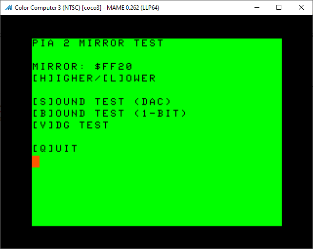
Pitfall One: The Busy Bit Is Active Low. So Is Everything Else.
The status byte at $FF7E has three active-low bits:
- Bit 7 ($80) – busy (low = busy)
- Bit 6 ($40) – speech active (low = speaking)
- Bit 5 ($20) – sound active (low = PSG making sound)
I initially wrote the busy-wait loop as:
bw1     lda     $ff7e
        bmi     bw1       ; wait while bit 7 set
But since busy is active low, bit 7 being set means not busy. The loop was waiting for the wrong condition. It would spin forever waiting for not-busy while the SSC was idle. The correct test is bpl (branch while plus), meaning while bit 7 is clear (busy):
bw1     lda     $ff7e
        bpl     bw1       ; wait while bit 7 clear = busy
Pitfall Two: The TMS-7040 Needs Time
The SSC uses a TMS-7040 microcontroller as an intermediary between the CoCo and all the other devices in the cartridge. When the CoCo writes a byte to $FF7E, it triggers an interrupt on the TMS-7040, which queues the byte and asserts the busy bit. When in the correct mode, the TMS-7040′s main loop then dequeues the byte and writes it to the PSG, then clears busy.
I assumed that the busy bit clearing meant the TMS-7040 was truly ready for the next byte. It is not. The busy bit clears before the microcontroller is fully ready to accept another write. If you send the next byte too quickly, it gets dropped silently.
The BASIC manual’s example program inadvertently works around this because the BASIC interpreter is slow. The overhead between a POKE and the next GOSUB is enough dead time that the TMS-7040 catches up. In tight assembly code, you have to add explicit delays.
Thru bisection I found that a delay loop of 49 iterations (at 8 cycles each, about 440 microseconds) was the minimum reliable inter-byte delay. I rounded up to 64 for safety. The WRPSG subroutine ended up looking like this:
WR2PSG
        ldx     #64
wp1lp   leax    -1,x
        bne     wp1lp
        pshs    a
bw1     lda     SSCDAT
        bpl     bw1
        puls    a
        sta     SSCDAT
WR1PSG
        ldx     #64
wp2lp   leax    -1,x
        bne     wp2lp
bw2     lda     SSCDAT
        bpl     bw2
        stb     SSCDAT
        rts
Pitfall Three: The Audio Is Not Routed Automatically
The CoCo has a sound multiplexer that selects the audio source for the internal speaker. By default it does not route cartridge audio. Before you can hear anything from the SSC, you need to configure the multiplexer:
*((unsigned char *)0xff01) = 0x34; // PIA 0 CA2 = 0 \_ Set mixer to CART
*((unsigned char *)0xff03) = 0x3f; // PIA 0 CB2 = 1 /
*((unsigned char *)0xff23) = 0x3c; // PIA 1 CB2 = 1 - Turn on sound
The BASIC example programs in the SSC manual does this as a matter of course, but it is easy to miss when writing a standalone C program. Without these writes, the PSG produces output that goes nowhere, and you hear nothing.
The Results
After working through all of those pitfalls, the test program finally ran correctly. The results from multiple runs on real hardware over a ten-minute thermal soak:
- Charge time: 740 iterations (approximately 8ms). Rock solid across all runs and the entire thermal soak
- Decay time: 12079-12163 iterations (approximately 133-134ms). Slowly increasing as the board warmed up, with ambient temperature affecting the value measurably. Running a fan near the CoCo during testing dropped the value by roughly 55 counts
The ratio of decay to charge is about 16:1, which is in the right ballpark compared to the schematic’s predicted 6:1. The difference is likely due to component variation in the actual capacitor and resistors on my particular board.
The most interesting finding is that the decay time is 134ms, not the 840ms predicted by the schematic. Either C25 has drifted significantly from its marked value over 40 years, or the board revision I own uses different component values than the schematic I was working from. Either way, real hardware measurements beat schematic theory every time.
The Revised Emulation
Armed with real numbers, I rewrote the Mame emulation. The original RMS circular buffer approach had several problems:
- The window size had no relationship to the circuit’s actual time constants
- It was sensitive to Mame’s buffer update rate
- The AY-3-8913 emulation produces a DC offset at idle which the RMS accumulated, making the circuit appear permanently active
- The threshold of 0.317 had no physical basis
The analog circuit is fundamentally asymmetric. C25 charges quickly through the rectifier diode but drains slowly through the resistor network. The correct digital model is an envelope follower with asymmetric attack and decay coefficients, preceded by a high-pass filter to remove the DC offset, matching the real circuit’s C9/R6 input filter.
void cocossc_sac_device::sound_stream_update(sound_stream &stream)
{
    int count = stream.samples();

    for (int sampindex = 0; sampindex < count; sampindex++)
    {
        float x = stream.get(0, sampindex);

        // High pass filter to remove DC offset (models C9/R6)
        float y = HPF_ALPHA * (m_hpf_prev_out + x - m_hpf_prev_in);
        m_hpf_prev_in = x;
        m_hpf_prev_out = y;

        // Envelope follower, asymmetric attack/decay (models C25)
        float rect = std::abs(y);
        if (rect > m_envelope)
            m_envelope += (rect - m_envelope) * ATTACK_COEFF;
        else
            m_envelope += (rect - m_envelope) * DECAY_COEFF;

        stream.put(0, sampindex, x);
    }
}

bool cocossc_sac_device::sound_activity_circuit_output()
{
    m_stream->update();

    if (m_sound_active && m_envelope < THRESH_OFF)
        m_sound_active = false;
    else if (m_envelope > THRESH_ON)
        m_sound_active = true;

    return !m_sound_active;  // active low
}
The attack and decay coefficients were derived from the hardware measurements and tuned against the emulated system:
static constexpr float HPF_ALPHA    = 0.99f;
static constexpr float ATTACK_COEFF = 0.0026f;  // models ~8ms charge time
static constexpr float DECAY_COEFF  = 0.0003f;  // models ~134ms decay time
static constexpr float THRESH_ON    = 0.05f;
static constexpr float THRESH_OFF   = 0.01f;
The envelope follower operates sample by sample, so it produces consistent results regardless of Mame’s buffer update rate or the user’s configured sample rate.
Conclusion
I have never encountered any CoCo software that actually polls the sound activity bit during normal operation. This entire exercise was in the service of correctness. If the hardware has the bit, the emulator should get it right.
The process turned out to be more interesting than I expected. What looked like a simple threshold comparison in the schematic revealed a carefully designed asymmetric envelope detector. And the busy-wait protocol had a hidden timing requirement. One that is documented in the manual, but easy to miss when writing tight assembly code.
If I had an oscilloscope, the waveforms on C25 charging and draining would have made a much better illustration for this post. Maybe next time.
The source code for the test program can be found here. The pull request for Mame is here.