Diecom Light Gun
Reverse Engineering the Diecom Light Gun Interface for the Color Computer
History
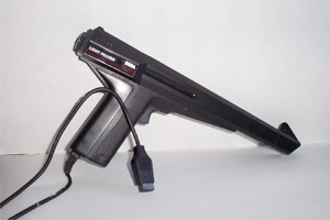
Diecom, a software company from Canada, produced and sold a light gun interface box. It let you attach a Sega Phaser (Model 3050) light gun to your Color Computer. Diecom also produced two games to make the gun useful: Iron Forest and Medieval Madness.
In Iron Forest there is a sample of Lori Dies saying "Welcome to the Iron Forest". I made a recording of that sample from the MESS emulator. Lori Dies is the sister of Diecom's Dave Dies. It is my understanding that the device was designed by Roland Knight.
Updated in November 2026. The first version of this page was written from the circuit board alone, and parts of it were wrong. This version was checked against the code inside both Diecom games and against the schematic below. The fixes also went into the light gun emulation in MAME.
How the adaptor works
The adaptor plugs into three places: the CoCo's serial port, the right joystick port, and the light gun. It has its own 9 volt battery.
- Serial port (input to the adaptor). The CoCo drives the adaptor with the RS-232 output, bit 1 of
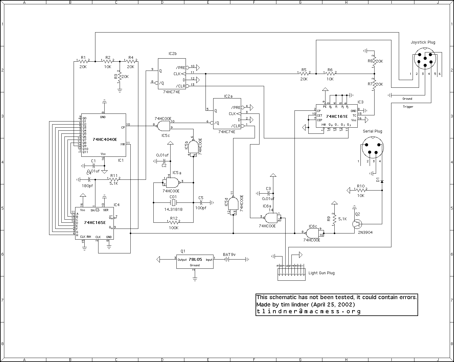
$FF20. Writing bit 1 from 1 to 0 advances a 4-bit counter (IC3, 74HC161), the adaptor's state, by one. While bit 1 is 0, the 12-bit timer (IC1, 74HC4040) is held cleared and the light detector latch (IC2a) is reset. While bit 1 is 1, the timer counts and the latch can catch light. - Light gun. When the gun sees the beam, the latch sets. That stops the timer, which counts the 14.31818 MHz crystal.
- Joystick port (output to the CoCo). The adaptor answers through the two joystick axes. Each axis is a two-bit resistor DAC: one signal is worth about 2.5 V and the other about 1.25 V. The CoCo reads them with its 6-bit joystick DAC and comparator. On that scale, 1.25 V reads as about 16 and 2.5 V as about 32.
| Joystick axis | 2.5 V signal | 1.25 V signal |
|---|---|---|
| Vertical (pin 2) | Light detected (IC2a) | Sync flag: state 15 (IC3 terminal count) |
| Horizontal (pin 1) | Timer bit 9 (IC1 Q9, wired directly) | Shift register output (IC4, 74HC165) |
The trigger is wired to the joystick button.
The CoCo reads timer bits Q1 through Q9. Bit Q0 is never used, so in effect the timer counts at 7.16 MHz. That is one count for every two pixels on a 640-pixel-wide screen, or one count per pixel in the 320-pixel modes the Diecom games use. Q1 through Q8 go into the shift register, and Q9 goes straight to the horizontal axis. Q10 and Q11 are not connected.
The shift register copies the timer continuously while the state is 0 through 7. From state 8 on, it holds whatever the timer said at the next light detection. Each later step of the state shifts out one more bit.
Writing a driver
This is the routine both Diecom games use, nearly byte for byte. "Pulse" means write bit 1 of $FF20 as 1 and then 0, which advances the state by one. The joystick DAC is bits 2 through 7 of $FF20, so you have to keep bit 1 correct whenever you set the DAC.
- Find state 15. Pulse the adaptor, then read the vertical axis, up to 16 times. Compare against 20 first. If it reads higher, the light flag happens to be set, so compare against 33. Otherwise compare against 5. When the sync flag shows, the adaptor is in state 15.
- Advance to state 7. Pulse 8 more times.
- Wait for a new frame. Sync on field sync (PIA0 CB1).
- Arm the gun. Write bit 1 = 1. This lets the timer run and arms the light latch. Set all 16 palette registers and the border to white (
$3F), so the gun sees light wherever it points. - Find the line. Start a counter at -50. On every HSYNC, read the vertical axis against 20. If it is high, the gun saw the beam on this line. Otherwise add one and keep going. If field sync comes around again first, nothing was hit.
- The counter is Y. The games treat it as the line within their 200-line screen. Y is 0 at the top and 198 is the largest value they accept.
- Restart the timer. Right after the hit is seen, write bit 1 = 0, wait about 50 CPU cycles, and write bit 1 = 1. This advances to state 8, clears and restarts the timer, and re-arms the latch.
- Let the timer stop. The timer now runs until the gun sees the beam again on one of the following lines. That second detection stops the timer and latches it into the shift register. Wait three HSYNCs so it has happened.
- Read bit 8. With the DAC at 20, read the horizontal axis. Only the 2.5 V signal (Q9) can reach 20, so this is bit 8.
- Read bit 0. Read the horizontal axis again: against 5 if bit 8 was 0, or against 45 if bit 8 was 1, since 2.5 + 1.25 V reads about 48. This is bit 0 from the shift register.
- Read bits 1 to 7. Pulse (state 9), then read against 5 to get bit 1. Repeat for bits 2 through 7 in states 10 through 15.
- The result is X. Subtract the game's offset to get X from 0 to 319 (see below). Restore the palette and leave bit 1 = 1.
The vertical position comes from software counting HSYNCs. The adaptor only says "light now". The horizontal position comes from the timer, but it is not measured from HSYNC. It is measured from the moment the driver restarts the timer in step 7. That moment is a fixed number of CPU cycles after an HSYNC, so the timer value still tracks the horizontal position, but its starting point depends on the driver's timing.
State table
The state is the number of 1-to-0 writes of bit 1, modulo 16.
| State | Horizontal, 2.5 V | Horizontal, 1.25 V | Vertical, 1.25 V | Notes |
|---|---|---|---|---|
| 0–6 | - | - | off | Shift register follows the timer. |
| 7 | - | - | off | Write bit 1 = 1 at the start of a frame and count HSYNCs until the light flag (vertical, 2.5 V) comes on. |
| 8 | bit 8 | bit 0 | off | Timer restarted; the next light detection latches it. Bit 8 is only available here, while bit 1 = 1. |
| 9 | - | bit 1 | off | Writing bit 1 = 0 clears the timer, but the value is safe in the shift register. |
| 10 | - | bit 2 | off | |
| 11 | - | bit 3 | off | |
| 12 | - | bit 4 | off | |
| 13 | - | bit 5 | off | |
| 14 | - | bit 6 | off | |
| 15 | - | bit 7 | on | Sync flag. |
The light flag (vertical, 2.5 V) can come on in any state while bit 1 = 1. It is cleared whenever bit 1 is written as 0.
Calibration: the two games disagree
Both games run the same routine but subtract a different number from the timer to get their X:
- Iron Forest subtracts 107.
- Medieval Madness subtracts 99.
Both games put their play area in the same place on the screen. So for the same spot, the two games' X values differ by 8 pixels. One possible explanation is that the games were calibrated on different machines or GIME revisions, since the timer's starting point depends on the CPU's timing. I have not confirmed this.
Emulation
MAME emulates the interface on the CoCo 3's right joystick port; choose "Diecom Light Gun Interface" in the controller settings. While writing this update I fixed several problems in MAME:
- The timer bits were shifted out one position off.
- The on-screen crosshair and the hit position used different coordinates.
- The timer's starting point is now set halfway between the two games' values, so each game is about 4 game pixels off in opposite directions.
With these fixes, the crosshair lines up with the targets in both games.
Hardware
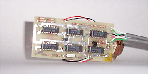
Here is a better close-up picture of the front.

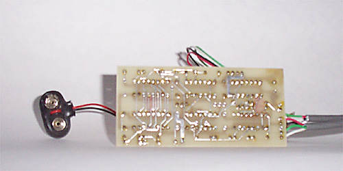
Here is a better close-up picture of the back.
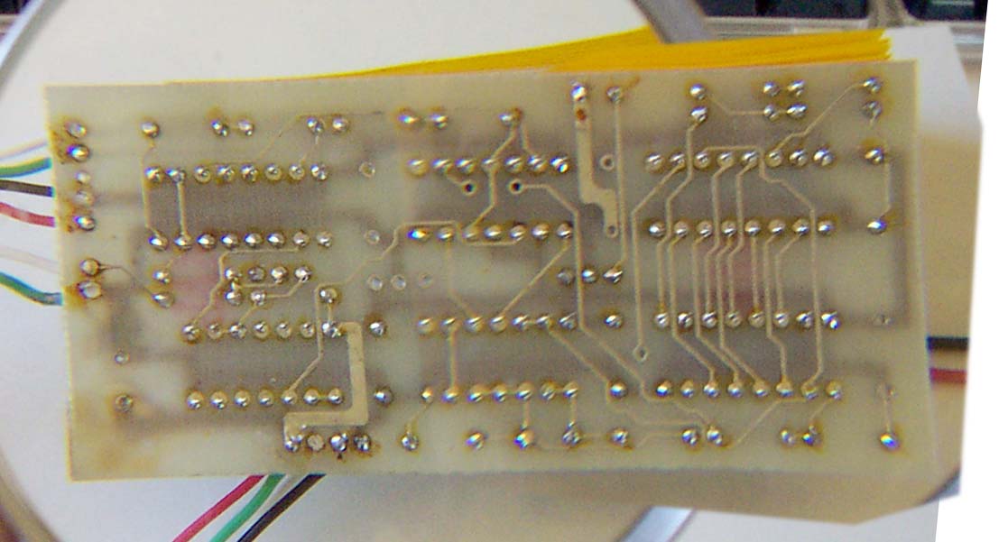
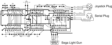
Printed circuit board layouts
PCB PDF:
PCB PDF with parts listed:
Parts
| Code | Part | Description |
|---|---|---|
| IC1 | CD74HC4040E | 12-bit asynchronous binary counter (the timer) |
| IC2 | CD74HC74E | Dual flip-flop (light latch and shift register latch) |
| IC3 | CD74HC161E | 4-bit binary counter (the state) |
| IC4 | CD74HC165E | 8-bit shift register |
| IC5 | CD74HC00E | Quad 2-input NAND gate (oscillator and timer gate) |
| IC6 | CD74HC00E | Quad 2-input NAND gate (gun and serial input) |
| R1, R3, R4, R5, R7, R8 | 20 k? (5%) | Resistors (R1–R4 horizontal DAC, R5–R8 vertical DAC) |
| R2, R6, R10 | 10 k? (5%) | Resistors |
| R9, R11 | 5.1 k? (5%) | Resistors |
| R12 | 100 k? (5%) | Resistor (oscillator) |
| C1, C2, C3 | 10 nF | Capacitors |
| C4 | 180 pF | Capacitor |
| C5 | 100 pF | Capacitor |
| Q1 | 78L05 ACP Motorola 652 | Voltage regulator |
| Q2 | 735 2N3904 (NPN) | Serial port level shifter |
| D1 | (no markings) | Diode |
| CO1 | FOX143 14.31818 | Crystal |
| 9 V battery connector | Misc. | |
| 6-pin DIN plug | CoCo joystick | |
| 4-pin DIN plug | CoCo serial | |
| 9-pin plug | Light gun |
Schematic
This schematic was drawn from the circuit board. The description above agrees with it and with the software.