History:
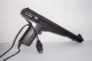
A software company from Canada (Diecom) produced and sold a light gun interface box. The interface allowed you to attach a Sega Phaser Model 3050 light gun to your Color Computer. They also produced two games in order to make the gun useful: Iron Forest and Medieval Madness.
In Iron Forest there is a sample of Lori Dies saying “Welcome to the Iron Forest”. I have made a recording of that sample from the MESS emulator. Lori Dies is the sister of Diecom’s Dave Dies. It is my understanding this devices was designed by Roland Knight.
Writing a software driver for the Diecom light gun adaptor
The adaptor is a 16 position state machine. The state machine is advanced by clocking the serial port from high to low.
The Interface Adaptor can send 4 signals back to the CoCo and any one time. Two bits are sent through the vertical axis of the joystick and 2 bits are sent thru the horizontal axis.
The first signal, called the state flag, is set high when the internal state machine is in state 15. This allows you to synchronize the adaptor’s state machine with the with the software driver you are writing. This signal is fed thru a 30 ohm resistor to the vertical joystick axis.
The second signal is the light detection signal. This signal is only available on state ‘High 7′. This signal is fed thru a 20 ohm resistor to the vertical joystick axis.
The next signal is from a serial shift register. It is connected thru a 30 ohm resistor to horizontal axis on the joystick.
The last signal is connected directly from pin 9 of the 12 bit counter to a 20 ohm resistor connected to the horizontal axis on the joystick.
The magic is started when the trigger/button is detected:
0. Wait for the start of a new video frame.
1. Change the display to all black. On the CoCo 3 in a hires mode, you can accomplish this quickly by changing all of the palette registers to black. Or you can change the base address of the video buffer that is set to all black.
2. Clock the Interface Adaptor to state ‘High 6′.
3. Wait for the next video frame.
4. Do two things: Setup the screen to display all white and clock the Interface Adaptor to state ‘Low 7′. This will start an internal 12 bit timer to start counting. The timer will stop as soon as the light sensor detects enough light.
5. At the end of the video frame, clock the Interface Adaptor to state ‘High 7′. You can now read the light detection signal on the vertical joystick port.
6. If you’ve detected light, clock the device to ‘High 8′ and bits 1 and 9 of the 12 bit counter will be available. Store them away.
7. Keep clocking the device and record bits 2 thru 8 of the 12 bit counter.
8. Now you will have a 9 bit number representing the time it took for the start of a frame to be drawn to when light is detected by the gun. A small number means the light gun was pointed at the top left of the monitor, a large number mean the light gun was pointed to the bottom right of the monitor.
| Clock | State | Pin 1 (30 ohms) | Pin 1 (20 ohms) | Pin 2 (30 ohms) | Pin 2 (20 ohms) | Notes |
| High | 0 | False | ||||
| Low | 1 | False | ||||
| High | 1 | False | ||||
| Low | 2 | False | ||||
| High | 2 | False | ||||
| Low | 3 | False | ||||
| High | 3 | False | ||||
| Low | 4 | False | ||||
| High | 4 | False | ||||
| Low | 5 | False | ||||
| High | 5 | False | ||||
| Low | 6 | False | ||||
| High | 6 | False | ||||
| Low | 7 | False | State 7 should be entered at the start of a video frame. The 12-bit counter willl be cleared and will increment until the beam is found. As soon as the video frame is over, clock high. | |||
| High | 7 | False | True if beam found | If the beam is found then bits 1-8 of the 12 bit counter are loaded into the shift register. | ||
| Low | 8 | Data bit 1 | False | |||
| High | 8 | Data bit 1 | Data bit 9 | False | Bit 9 is only avaiable here. On the next clock the 12-bit counter will be cleared. Data bits 1-8 are safetly stored in the shift register. Bits 0, 10 and 11 are not avaiable to the Color Computer | |
| Low | 9 | Data bit 2 | False | |||
| High | 9 | Data bit 2 | False | |||
| Low | 10 | Data bit 3 | False | |||
| High | 10 | Data bit 3 | False | |||
| Low | 11 | Data bit 4 | False | |||
| High | 11 | Data bit 4 | False | |||
| Low | 12 | Data bit 5 | False | |||
| High | 12 | Data bit 5 | False | |||
| Low | 13 | Data bit 6 | False | |||
| High | 13 | Data bit 6 | False | |||
| Low | 14 | Data bit 7 | False | |||
| High | 14 | Data bit 7 | False | |||
| Low | 15 | Data bit 8 | True | |||
| High | 15 | Data bit 8 | True | |||
| Low | 0 | False |
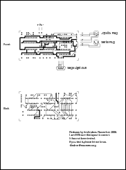
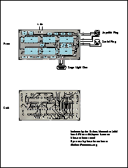
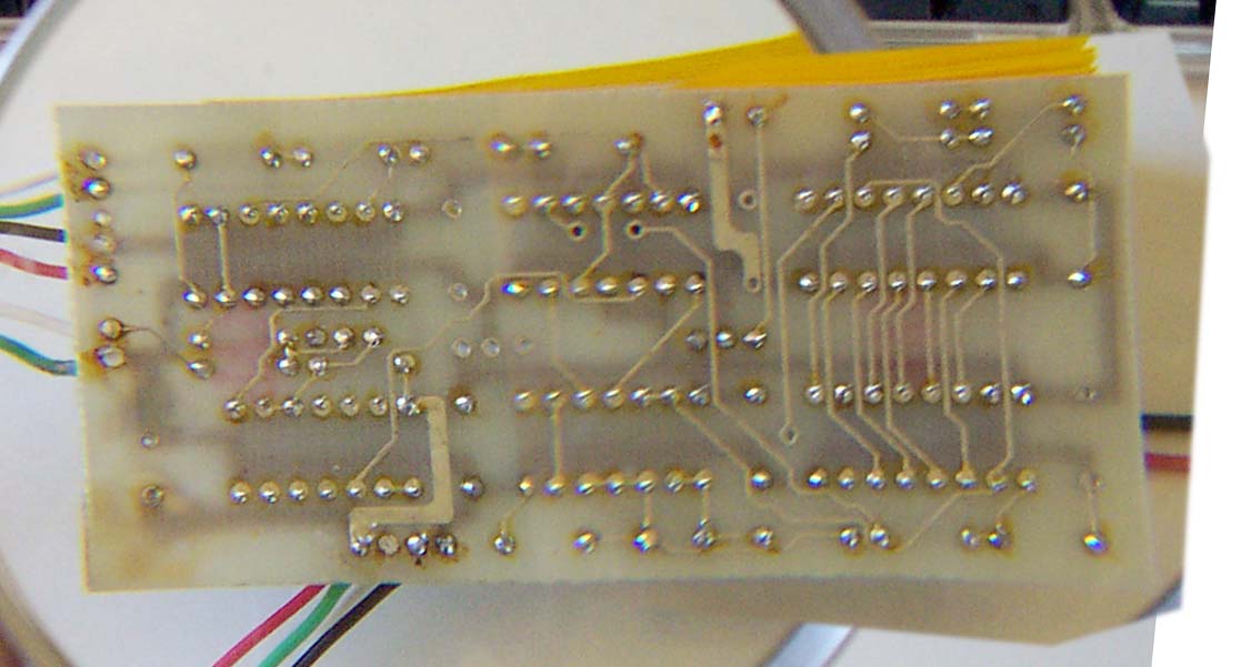
Hardware:
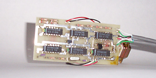 Here is a better close-up picture of the front. 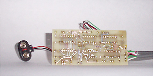 Here is a better close-up picture of the back. Here is a better close-up picture of the back.
Printed Circuit Board Layouts:
Schematic (preliminary): |